


 Price is 8-20% Lower Than Other


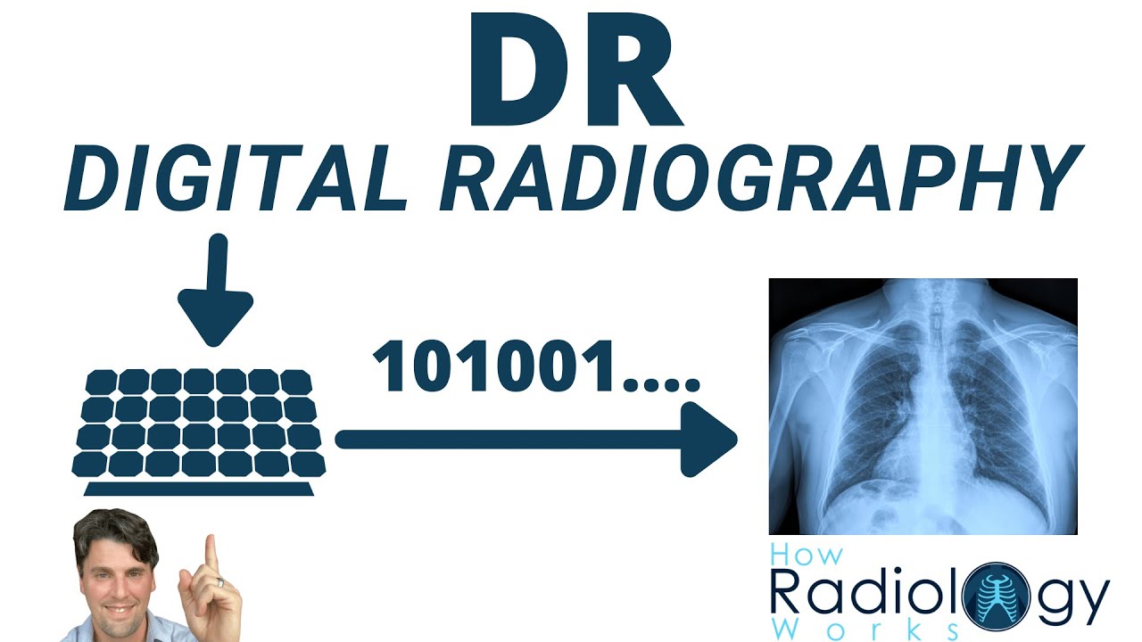
Digital Radiography (Direct vs Indirect Flat panels)
Digital radiography detectors are used to directly acquire x-ray images in place of film or computed radiography (CR) systems and are separated into direct and indirect detectors. Direct detectors convert from the x-rays electrons (that are measured), whereas indirect detector convert from x-rays to visible light first and then to electrons (that are measured).
Digital detectors are also used for fluoroscopy, interventional and mobile x-ray systems in place of image intensifier systems.
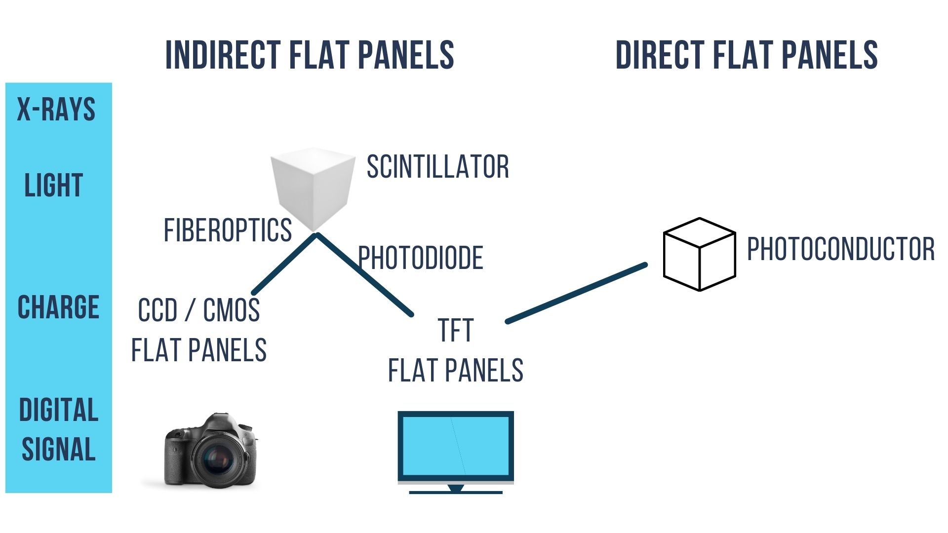
Digital Radiography (DR) detectors are classified as indirect flat panels or direct flat panels based on the underlying physics for each type of panel. Indirect flat panels convert x-rays to light photons that are then measured by a CCD/CMOS or Si photodiode and TFT array. Direct flat panels convert the x-rays directly to electrons that are measured by a TFT. Direct flat panels achieve higher spatial resolution by skipping the visible light step that can blur the images as the light spreads.
The first figure demonstrates the different categories of flat panel detectors where there are two categories indirect and direct. The indirect flat panels are further differentiated into the TFT type and the CCD/CMOS type. In the figure and comparison table we highlight the main differences which are that the CCD/CMOS type require fiber optics and the TFT type uses an array of photodiodes.
In the upcoming sections we describe the steps needed to generate an image by each type of detector. These are all flat panel detectors but we will illustrate the steps from the x-ray interaction to the digital signal using small illustrations, but we should keep in mind that these interactions are all are occurring in flat panels with many neighboring detector elements (i.e. typically 1024×1024 detector elements or more).
|
Indirect Flat Panel (TFT) |
Indirect Flat Panel (CCD) |
Direct Flat Panel |
|
|---|---|---|---|
|
X-ray capture |
Scintillator (CsI,GOS) [to light] |
Scintillator (CsI,GOS) [to light] |
Se Photoconductor [to electrons] |
|
Focus light |
Not needed |
Fiberoptics |
Not needed |
|
Light to charge |
Si Photodiode |
CCD |
Not needed |
|
Charge storage/readout |
TFT |
CCD |
TFT |
Indirect flat panels measure the x-ray signal by converting from x-rays to: visible light, to charge (i.e. electrons) and then to the digital signal. Direct flat panels skip the visible light step and the x-rays are converted directly to electrons, and then the charge is digitized.
Which Scintillator GOS or CsI is better for Flat X-ray Detectors?
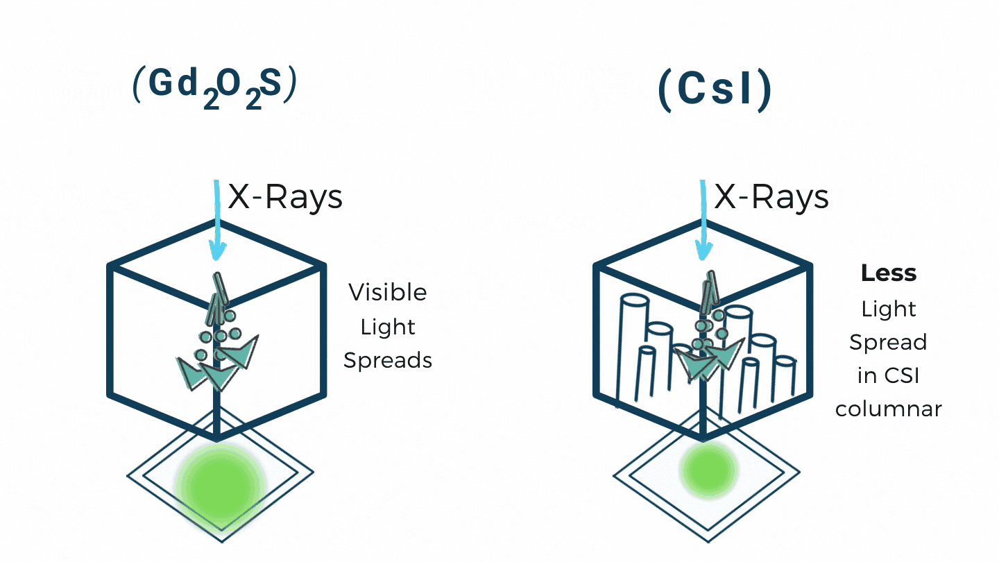
There are some types of crystals which absorb x-rays and produce visible light. These are called scintillators and they are the first step in indirect panels. The two most frequently used materials for the scintillation layer are Gd2O2S (Gadolinium OxiSulfate, also know as: GadOx or GOS) and Cesium Iodine.
GOS is less expensive than CsI and provides good light output but the light will spread out resulting in a blurring of the light signal that will be measured in later steps.
CsI on the other hand has less light spread since the crystal has a columnar structure so the light will follow the columns of the CsI as it passes through the crystal. This reduced blurring leads to higher spatial resolution for CsI based systems compared with GOS systems.
|
Scintillation Comparison |
Expense |
Spatial Resolution |
Fiber Optic Coupling |
|---|---|---|---|
|
Gd2O2S |
$ |
+ |
– |
|
CsI |
$$ |
++ |
+ |
Additionally, one of the types of flat panels (Indirect CCD type) requires the light to be focused down, with a fiber optic for instance, to a smaller size to be measured on the CCD. The light coming from GOS has more spread in the direction as well which makes it difficult to focus. For this reason CsI is more frequently selected for CCD type flat panel systems.
For general purpose radiology systems both GOS and CsI are acceptable choices for the scintillation layer is based on the trade-off of cost vs spatial resolution.
How do Indirect TFT Flat Panels Work?
The most common type of Digital Radiography system is the Indirect flat panel that is read out with an array of Thin Film Transistor (TFTs). TFT flat panels use the same basic technology that are used to control LCDs (Liquid Crystal Displays) in many common flat panel monitors and TVs. The TFT array enables each pixel in an LCD to be turned on and off independently and likewise when it is used in an x-ray detector it allows each detector element (DEL) to be read out independently.
In this figure you can see the input x-rays are first converted to visible light. Each x-ray is converted to many light photons and these light photons spread out as they pass through the panel. As we described above the most common scinitillators are based on either Gadolinium based (e.g. GOS, Gadox, Gd2O2S) or Cesium Iodine (CsI).
The visible light photons are then measured on a photodiode that converts from the light signal to an electrical signal. The photodiodes are typically made of amorphous Si. When the light photons hit the photodiode they produce electron and hole pairs.
The material for the photodiode (Si) is chosen because the light photons coming out of the scintillator are best matched to generate a photocurrent, i.e. a current from the energy transferred from the light. This is due the the material properties (i.e. the bandgap of Si).
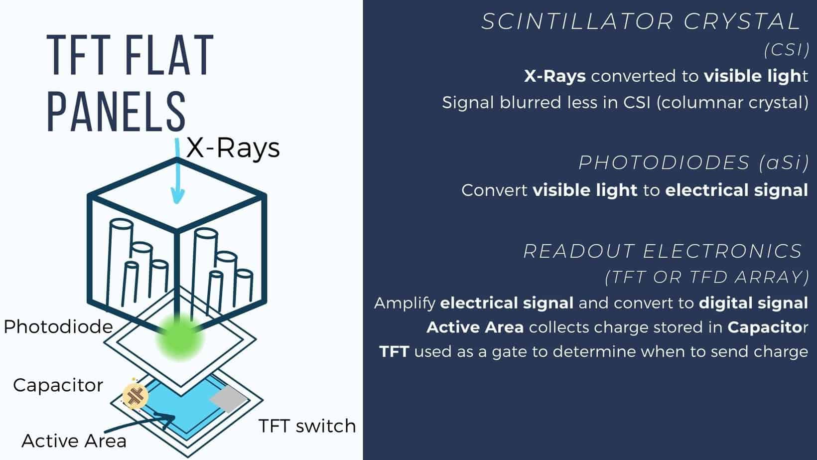
Finally, after the photodiode converts the light to an electrical signal a TFT (thin film transistor) array is used to readout the measured charge. The TFT array is based on a glass substrate and silicon is deposited as a conductor to connect parts of the circuit. Additionally silicon dioxide is used as an insulator to build up the circuit so that all of the electronic circuits are flat and built-in to the TFT.
Each detector element in the TFT stores the charge in a capacitor and uses a TFT switch or gate to control when the charge is read out.
Within each detector element (DEL) there is an active area shown in blue in the figure. This is the region where change can actively be deposited. There is also the need for some other electronics such as a capacitor (to store the charge) and a TFT switch (to open up when it is time to readout the value from that DEL).
The extra electronics including the capacitor and the switch take up some of the space, and they can’t shrink in size at the same rate as the detector element. Therefore, as the size of the detector elements get smaller the relative fraction of the DEL that is the active area (i.e. the fill fraction) shrinks. We have another post dedicated to the terminology of digital detectors as you know you want to learn more about the active area, fill fraction, detector pitch and matrix size.
Since the signal is read out from the active area a higher fill fraction is desired and leads to a more efficient detector as more of the x-rays that pass through the patient will contribute to measurements on the detector. This efficiency contributes directly to the dose efficiency of the system. This factor limits how small each individual DEL can be as we also want high dose efficiency.
A higher fill fraction helps with the efficiency of the acquisition. However fill fraction does not lead to improved spatial resolution. To achieve improved spatial resolution due to the detector the size of the DEL needs to be reduced, since the spatial resolution is heavily influenced by the effective size of the pixels. The resolution of any x-ray system is also influenced significantly by the focal spot blurring.
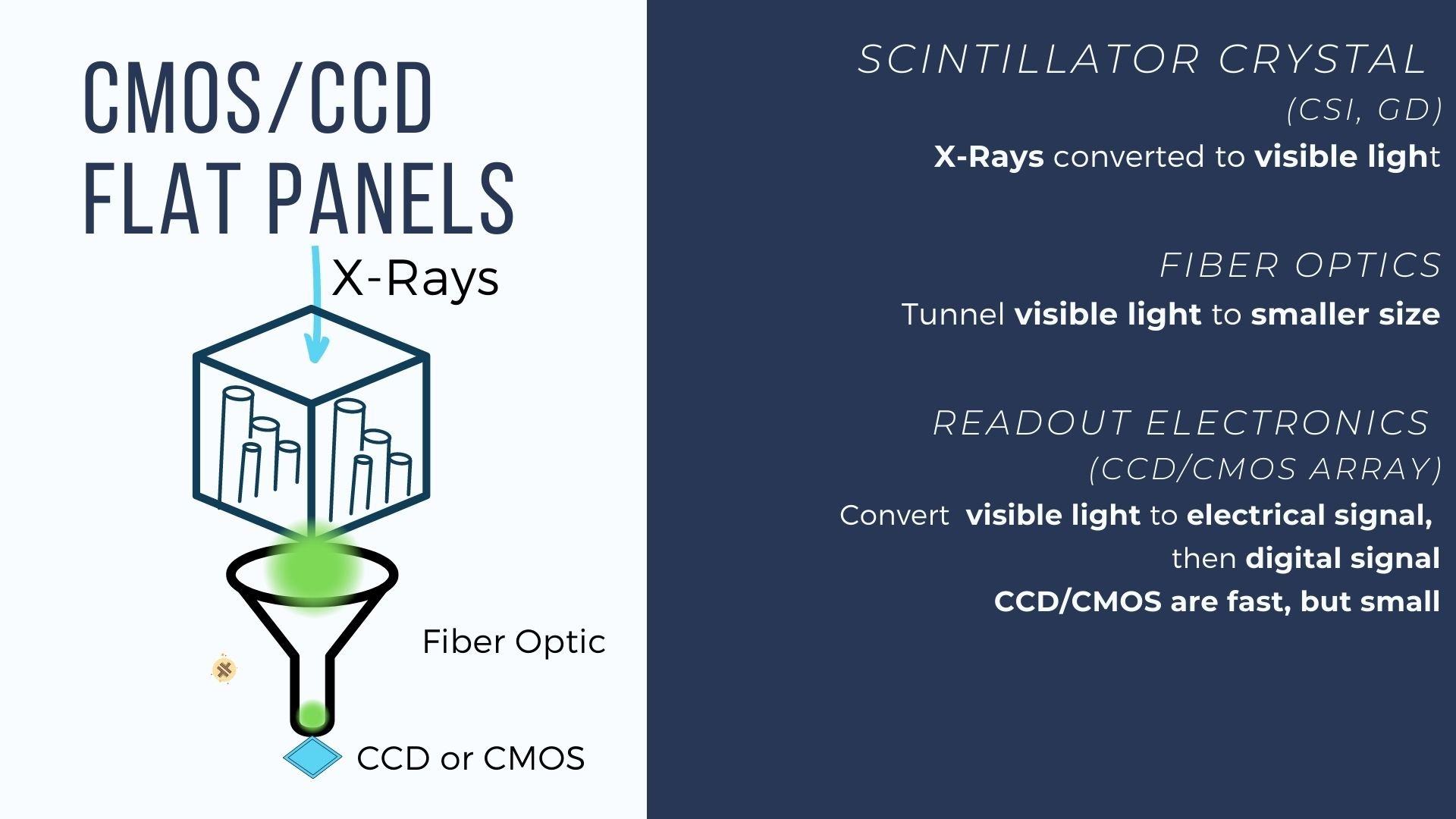
How do Indirect CCD Flat Panels Work ?
The other alternative for an indirect flat panel detector is to make use of the technology that is used in digital cameras, namely CCDs (Charge Coupled Devices) or CMOS (Complementary Metal-Oxide-Semiconductor). CCDs are well designed for the purpose of measuring visible light as they are used as the sensor on many digital cameras. CCDs also have the advantage that they can be read out quickly. However, unfortunately the size of the CCDs does not match the size of the flat panel detector.
To connect the visible light from the scintillator to the CCD or CMOS detector fiber optic coupling can be used as a light funnel to take the light from the larger size of the scintillator area down to the smaller size of the CCD. Not all of the visible light is funneled down to the CCD leading to a slight reduction in efficiency compared with the TFT flat panel. Lenses or electron-optic coupling may also be used in place of the fiber optics to demagnify the signal.
The major strength of the CCD and CMOS technology is the readout speed, as the electronics in the CCD enable the detector to be read faster than traditional TFT arrays. This is particularly beneficial for interventional and fluoroscopy imaging where the frame rates (i.e. how many images are taken a second) are much more demanding than traditional radiography.
How do Direct Flat panel X-ray detectors work?
Direct flat panel detectors use a completely different physical interaction mechanism to convert the x-rays to a measurable signal. In direct flat panel detectors the x-rays are converted directly into electron and hole pairs, skipping the visible light step that is needed in indirect detectors.
Direct flat panel detectors are based on flat panels of amorphous selenium (aSe) which is the material that the x-rays will interact and generate electron and hole pairs.
To date the CCD sensors have dominated in this space as they are ubiquitous but we include CMOS here as well as these sensors may gain more traction in the near future if CCD production slows. But from your perspective as a radiologic technologist the CCD and CMOS can be considered as similar technology and will be used within an indirect flat panel system along with fiber optics to funnel down the visible light.
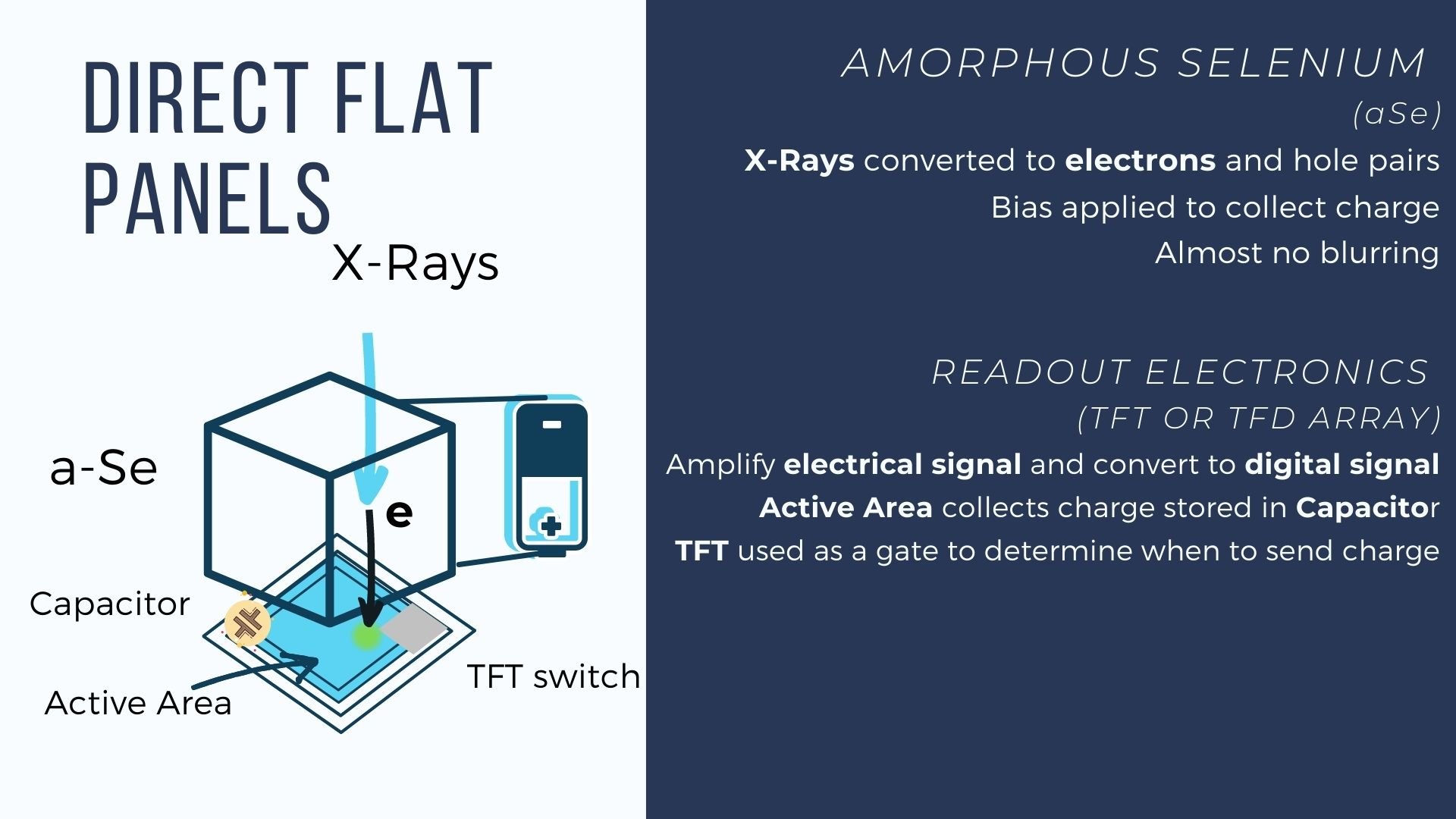
A voltage is applied across the detector such that the electrons will flow to one side and the holes will flow more slowly to the other side. The electrons which are pulled directly to the positive side can then be measured. This flow of electrons is also referred to as an electric current.
The electrons are then collected within the active area of a TFT array and the charge collected is stored within a capacitor for each detector element. The TFT contains the electronics to amplify the analog electrical signal and convert it to a digital signal. TFTs have individual switches or gates at each detector element so that they can each be readout separately.
|
Indirect Flat Panel (TFT) |
Indirect Flat Panel (CCD) |
Direct Flat Panel |
|
|---|---|---|---|
|
Resolution |
+ |
+ |
+++ |
|
Readout speed |
++ |
+ |
– |
|
Low Dose Readout |
+ |
– |
+ |
|
Cost |
$$ |
$ |
$$$ |
|
Best applications |
Fluoroscopy/General |
General Radiography |
Mammography |
The major advantage of direct flat panel detectors is that the electrons do not spread nearly as much as visible photons. This results in a higher resolution for direct flat panel systems, even when the size of the detector elements is the same.
The aSe used in direct detectors is not as efficient in stopping higher energy x-rays that are used to image abdomens of larger patents for instance.
Therefore, direct flat panel detectors are particularly well suited for mammography where there is a need for very high spatial resolution and the x-ray beam is relatively soft (e.g. low energy x-rays).
Which type of Digital Radiography (DR) Flat Panel x-ray detector is the best?
The best flat panel digital radiography system will be dependent on the application. There are always special cases for certain systems but in general our recommendations are below.
Angiography/Fluoroscopy->TFT Indirect Flat Panel Detectors
Mammography->Direct Flat Panel Detectors
General Purpose Radiography->TFT or CCD based Indirect Flat Panel Detectors
In the table below we compare the major factors in this comparison that include: image resolution, readout speed, and cost.
The systems with the highest resolution are the direct flat panel systems as these systems can skip the blurring step of generating visible light. These systems are also the most expensive and are not the most efficient at collecting high energy photons. Since resolution is very important in mammography to visualize micro calcifications the direct flat panels are the best choice for mammography applications.
The indirect flat panels have comparable resolution. For general purpose radiography the TFT based (same technology as flat panel monitors) flat panel imagers are the most ubiquitous given that they are efficient and get the job down without breaking the bank. The tradeoff is that TFT are generally slightly more dose efficient and slightly more expensive than CCD indirect flat panel imagers.
For angiography applications and other fluoroscopy the CCD panels are capable of fast readout but at low radiation doses of fluoroscopy the TFT detectors are preferred since the CCDs are not as efficient with low radiation dose levels.


